Debugging, Finite State Machines, and Wall-Following
Today
- Brainstorming Robot Debugging Strategies
- Finite State Machines
- ROS Params and Wall-Following
- Studio Time (Wall-Following)
For Next Time
- Work on the the RoboBehaviors Project, due Sept 22nd at 7PM!
- In-Class Shareout: September 21st, 1PM (Canvas description)
- Project Due Date: September 22nd, 7PM (Canvas description)
- Individual Survey: September 22nd, 9PM (Canvas description)
- By next class, it is recommended that:
- You have implemented your wall-following behavior
- You have a working prototype of your finite state machine
- You are prepared to share your in-class update
- Your write-up is nearly complete
- Work on your Broader Impacts assignment (Due Sept 29th at 7PM).
- We will have a class discussion on Thursday Oct. 1st.
Brainstorming Robot Debugging Strategies
Debugging is the act of incrementally testing code for accurate behavior and tracing errors back through the system to resolve them. You may have encountered some debugging strategies in SoftDes. Some generic strategies for debugging software carry over to robotics programming, while novel methods may need to be included given the interaction software has with hardware.
Group Discussion
Take 10 minutes to come up with some debugging strategies for writing robotics code with the folks around you based on your experiences in this class so far, then we’ll share out to the class. As a motivating example, let’s consider the part of the RoboBehaviors where you have to create a wall follower.
Here are some areas to consider in the debugging / development lifecycle:
- How do you ensure your code is correct (implements the strategy you expected)?
- How do you test your approach to see if it performs the task effectively (e.g., follows a wall)?
- How might you tune the parameters of your approach to make it perform as best possible?
For Your Projects
For your RoboBehaviors project, ensure that you have implemented some debugging strategies – print things to terminal or log them, include special topics for visualization, implement tests. Do not delete your debugging tools when submitting your final product.
Finite State Machines
We have been working on developing singular robot behaviors over the last few classes. But what if we want to chain behaviors together into more complex interactions with an environment?
While there are many possible frameworks to utilize, finite state machines represent a fundamental way to switch between different actions depending on environmental (or internal) measurements.
Consider the following example from the project assignment:
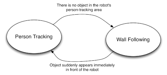
Here, the circles represent “states” that our robot can be in; in this case, a behavior that it can be executing. The arrows represent “transitions” between states, with the “transition criteria” labelling the arrow.
Finite state machines, by their name, imply the following:
- There are a finite, countable number of states that a robot can be in
- Each state is deterministic (that is, we know with certainty what state we are in)
- Given the current state of the robot, a transition to another state is deterministic based on a unique transition criteria
Here, while there are two states and two transition criteria, and there is a cycle, you can have finite state machines such that there are multiple transition criteria that can lead to different states, you can have “terminal states” where once the robot arrives in that state it stays in that state forever, and you can have internal cycles within a larger network. While they may be finite and deterministic, finite state machines can capture incredibly complex behavior – their limitation is realistically your own imagination (since everything must be explicitly defined).
Outside of class, you and your partner have already started to design a finite state machine for your project; with your partner now, please:
- Draw your proposed FSM on the board – make sure to label states and transition criteria specifically
- Under your diagram, note how you’re thinking about implementing your finite state machine (single-threading, multi-threading, special publish/subscribe frameworks, etc.). A common dichotomy you could consider:
- Many nodes, one manager: You are running behaviors in N separate nodes, and you have one “manager node” running your FSM to coordinate between which nodes are “active” over the ROS network.
- One node, many callbacks: You run a single FSM node with the behaviors directly embedded as functionality in the FSM, accessed by a system of internal callbacks for managing what functions are accessed based on internal record keeping of states and transitions.
You will share your plans with a few other teams, an opportunity for quick feedback and questions.
ROS Params and Wall-Following
Simplify: Wall Approach
Wall-following is complicated (it can be represented as a finite-state-machine!), so it is useful to break it down into smaller or simpler projects. We’re going to walk through one sub-component of wall-following: Wall Approach.
Let’s consider your distance_emergency_stop from a few classes ago – we’re going to go ahead and adapt this into a wall-approach node.
To get started, create a package somewhere in your ros2_ws/src directory for your work. In this example, we can put the package directly in ros2_ws/src/class_activities_and_resources directory then rebuild the workspace:
$ cd ~/ros2_ws/src/class_activities_and_resources
$ ros2 pkg create in_class_day05 --build-type ament_python --node-name wall_approach --dependencies rclpy std_msgs geometry_msgs sensor_msgs neato2_interfaces
$ cd ~/ros2_ws
$ colcon build --symlink-install
$ source ~/ros2_ws/install/setup.bash
You may have noticed at this point that ROS requires a certain amount of boiler-plate code to get going. From here, you have three choices for development:
- Write everything from scratch
- Start with your
distance_emergency_stopcode - Start with this example code
We would like to program the Neato to adjust its position so that it is a specified (target) distance away from the wall immediately in front of it. The Neato’s forward velocity should be proportional to the error between the target distance and its current distance.
With your project partner(s), consider the following:
- What variables do you need to define?
- When you get a Lidar measurement, how will you compute error?
- How will your transform your error into a velocity command? (hint: consider the sign of the error and your velocity; consider the maximum velocity that the Neato can travel.)
Go ahead and implement your proportional controller within your wall_approach node.
You can use this link to find a sample solution to this task.
Getting Fancy: ROS Params
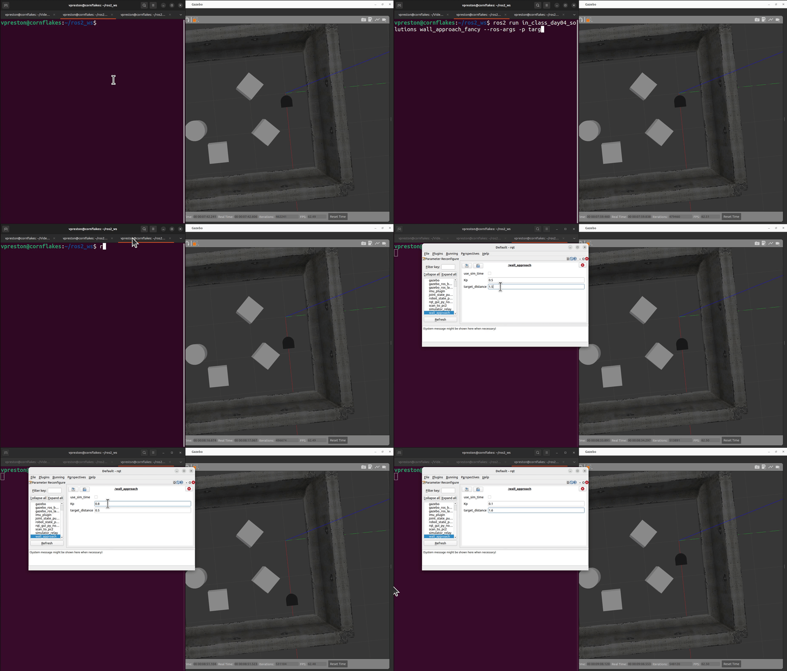
To make a node more configurable, you can use ROS Params, which allow us pass in arguments to a node from the commandline (or control them through tools like rqt). This is super powerful, because it can let you, in real time, adjust your robot performance and behavior without killing, re-writing, and re-running your nodes. For proportional control, we could set our proportional coefficient and our target wall distance in this way, allowing us to tune our robot’s behavior without having to relaunch the code tons of times.
- See the ros param command line tools documentation for more information
- Code for accessing parameters in Python documentation from The Robotics BackEnd (which might be a bit easier to parse than the official one).
For instance, if you follow the documentation you can create a node similar to our sample solution, wall_approach_fancy.py that supports the following customization via the command line:
$ ros2 run in_class_day05_solutions wall_approach_fancy --ros-args -p target_distance:=1.5 -p Kp:=0.5
Here is a demo of the script, wall_approach_fancy.py that uses ROS parameters as well as the tool dynamic_reconfigure for easy manipulation of various node parameters.
Note that in order to support
dynamic_reconfigurein your nodes, you have to calladd_on_set_parameters_callbackand implement an appropriate callback function (see sample solution for more on this).
Adding Complexity: Wall-Following (Studio Time)
When you feel like you have a sense of the example code, or have working sample code of your own for wall-approach, consider how you might adjust the code to work for wall-following (approaching and driving parallel to a wall at a certain distance). Have a look at the assignment document for a sample diagram (hint: you might want to draw a lot of pictures before you think about coding anything).
With your project partner(s) specifically consider the following:
- How does the robot know what angle it is relative to the wall? How will you parse a Lidar message into an angle?
- How should the robot drive if it is too far from the wall? Too close from the wall?
- How will you compute error in your robot’s relationship with the wall? How should error control linear velocity? Angular velocity?
- How will you architect your wall-following behavior as a node?
- How will you test you wall-following behavior?